
Abstract: The principle and application of POE technology are briefly introduced. Then according to the different video signal transmission systems, the current video surveillance systems are classified and their characteristics are briefly introduced. A marine network based on POE technology is proposed. The hardware design scheme of the video surveillance system. The scheme divides the whole network video surveillance system into three parts according to the function, and elaborates the composition and design principle of each part. Finally, the main features of the video surveillance system and its Later promotion and application have been evaluated accordingly.
0 Preface
POE (Power Over Ethernet) is also known as LAN-based power supply system or Active Ethernet, sometimes referred to as Power over Ethernet. This is the simultaneous transmission of data and electrical power using existing standard Ethernet transmission cables. The latest standard specifications and maintain compatibility with existing Ethernet systems and users. POE technology transmits data signals for some IP-based terminals (such as IP phones, WLAN access points, APs, network cameras, etc.) It can also provide DC power supply technology for such devices.
While ensuring the security of existing structured cabling, ensuring the normal operation of the existing network and minimizing costs. A complete POE system includes Power Sourcing Equipment (PSE) and Powered Device (Powered Device, PD) Two parts. The PSE device is the device that powers the Ethernet client device and is also the administrator of the entire POE Power over Ethernet process; the PD device is the PSE load that receives the power supply, that is, the client device of the POE system.
1 Introduction to video surveillance system
The video surveillance system can be divided into two major categories: analog video surveillance system and digital video surveillance system according to the different video signal transmission systems. The block diagram of the analog video surveillance system is shown in Figure 1.
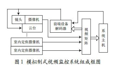
The analog video surveillance system shown in Figure 1 is mainly composed of front-end equipment (camera, lens, cloud, decoder, etc.), video matrix and monitoring system host. The video matrix is ​​generally in the same installation position as the host, video. The analog to composite video signal is transmitted between the matrix and the front-end device. The analog composite video signal is collected by the front-end device and transmitted to the monitoring host via the video matrix. The control signal of the monitoring host is transmitted to the decoder through the serial port and decoded by the decoder. At present, the control of the front-end equipment is realized. At present, the analog video surveillance system mainly has the following characteristics: First, the number of cables and components is large, and it is not suitable for long-distance transmission. When the fault is encountered, the efficiency is low; second, the scalability is poor; It is poor compatibility and is not conducive to resource integration with other devices.
In recent years, with the rapid development of computer, network and image processing and transmission technology, video surveillance technology has developed rapidly. The analog video surveillance system has been gradually replaced by networked digital video surveillance system. Shown.
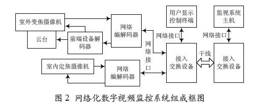
The networked digital video surveillance system in Figure 2 is mainly composed of user display control terminal, access/switching device, network codec, front-end device (camera, lens, pan/tilt, etc.). The video information collected by the camera is recorded. The network codec is digitized and output to the network interface board of the access/switching device, and then enters the trunk network transmission via the access/switching device. After the user terminal is authorized, the user terminal can view and control the control signal of the terminal through the access/exchange The device. The network codec is sent to the decoding front-end device decoder, and the decoder is decoded to realize the control of the front-end device.
Because the monitoring front-end equipment adopts distributed access and distributed processing, the workload of the networked digital video monitoring system host is greatly reduced. At the same time, because of the openness of the system, the switching subnet and the resource subnet are independent and exchanged. The subnet provides an open interface to the resource subnet, which also provides unlimited possibilities for the scalability of the post-monitoring system.
2 Design of marine network monitoring system based on POE technology
In view of the above characteristics of the traditional monitoring system, combined with the current mature POE technology application, the hardware system design scheme of a new network video surveillance system for marine is proposed.
The system hardware equipment mainly includes front-end equipment (indoor integrated machine, outdoor cloud platform, outdoor camera, protective cover, etc.). Access/switching equipment. System host and multi-user terminal are four parts; the system composition is shown in Figure 3.
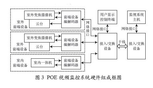
According to Figure 3, the power supply of the outdoor camera PTZ integrated machine and the indoor camera PTZ integrated machine is provided by the access/switching device with POE function, and the control of the PTZ and the camera is sent by the user display control terminal or the host through the network interface. To the access/switching device, enter the trunk, and then route through the switching device. After transmission, it is output to the corresponding access/switching device network interface board, and then identified by the corresponding front-end device and output to the corresponding front-end device. The video information collected by the camera is digitized by the front-end device codec and output to the access/switching device via the network interface, and then enters the trunk through the access/switching device. The user display control terminal can be viewed after being authorized. The following briefly describes the system. The design principle of each major extension.
2.1 Front-end device design principle
The front-end equipment is mainly divided into indoor and outdoor types: the indoor front-end equipment is mainly composed of the camera pan-tilt machine and the front-end device codec; the outdoor-type front-end equipment is mainly composed of the front-end device codec. camera. lens. The shield is composed of several parts. Among them, except the front-end device codec needs to be designed by itself, the other components can be directly purchased. The front-end device codec is a codec with PD function. For compatibility, the indoor and outdoor front-end equipment adopts the same model. Codec. Considering the windproofness of outdoor equipment, the maximum load capacity of the pan/tilt is 5 kg and the maximum power is 30 W; the power of the camera and lens is about 15 W, so the maximum power of the power supply is 45 W. This design uses MAX5986 as the power supply controller of Ethernet. It can provide single-ended maximum power output of 70 W, which can meet the power supply requirements of indoor and outdoor front-end equipment. Figure 4 shows the design schematic of the front-end device codec.
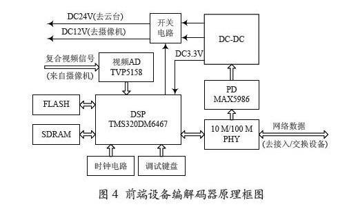
As shown in Figure 4, the front-end device codec is mainly composed of video AD (TVP5158). DSP video processing chip TMS320DM6467.PD power take-off circuit (MAX5986 circuit) and DC-DC circuit.
The composite video signal from the camera is sampled and converted by video AD (TVP5158) and output to the DSP via the bus. (The TMS320DM6467 used in this design is a DSP/ARM9 architecture digital media system-on-chip. It is a new DaVinci technology digital media from TI. The processor is outputted by the corresponding format compression encoding, and then sent to the access/switching device via the Ethernet peripheral integrated by the DSP on-chip system, and then enters the trunk transmission. The user display and control terminal control information is connected. The POE-capable network interface board of the incoming/switching device is sent to the physical network interface of the front-end device, and the MAX5986 is routed for power-receiving. The DC-DC is converted to a codec. The camera, the lens, the pan/tilt, etc. are powered; It is controlled by its on-chip ARM9 processor to realize data decoding and realize the control of the camera. PTZ. The debugging keyboard is used for the front-end device to be debugged separately.
2.2 Monitoring system host principle
The monitoring system host mainly completes the recording of the front-end equipment. The access of other equipment video signals. The monitoring and management of the entire monitoring system. Mainly by an industrial computer. Video acquisition and processing card. Large-screen surveillance TV wall and hard disk array The long-term video recorder is composed of several parts. It can be solved by purchasing components. The host computer controls and manages the monitoring system by installing video monitoring software.
2.3 Access/Switching Equipment POE Power Supply Network Interface Board Design Principle
The schematic diagram of the POE power supply network interface board of the access/switching device is shown in Figure 5.

As shown in Figure 5, the network access/switching device network interface board mainly implements network access of the front-end device and network switching between the user terminal and the front-end device. The network interface board is mainly cached by the SGRAM of the switching control chip VT6510.2M. POE power supply control chip MAX5982. Microcontroller STM32F103 and related peripheral components. Among them, VT6510 switch chip integrates 8 10/100 Mb/s switch ports and 2 Gigabit switch ports into a single control chip, which conforms to the latest IEEE network standard. , including 802.3x flow control. VLAN function. High-performance switching engine and IP multicast function, can complete 8-port 10M/100M adaptive network non-blocking switching. Store and forward.
E2PROM is mainly used to save the configuration data of the switching device. When the device is powered on or reset, the device will read out the data from the E2PROM for system initialization. The microcontroller uses the ARM7 architecture STM32F103 to complete the reading and writing of the registers. The communication between the PCs can be configured into various working modes to meet the needs of different users. The MAX5982 is a POE power supply control chip, which cooperates with the rectifier voltage regulator circuit to complete the PSE device function.
3 Conclusion
In summary, the network video surveillance system based on POE technology has the characteristics of digitization, intelligence, automation and networking, and its excellent scalability, manageability and easy integration with other systems make it greatly Simplify and improve the way and speed of information transmission. With the continuous development of network technology and computer technology, network video surveillance system based on POE technology and video exchange technology will become the new standard of ship monitoring system.
Stair Railing,Balcony Railing,Aluminum Extension Ladder Railing
Steel Grating,Miscellaneous Co., Ltd. , http://www.steel-grating-manufacturer.com