
Abstract: This paper mainly describes the application of photovoltaic power generation and ZigBee protocol in home intelligent anti-theft system. In order to achieve the purpose of alarm, the body temperature of the human body is detected by the infrared sensor, and the signal is transmitted to the host via the wireless sensor network through the low-power 2.4 GHz chip JF24C. After the host computer calculates the alarm signal and notifies the owner through the GSM network; The method of supplying energy to the dual power system of the household power source not only saves the environment and saves energy, but also improves the safety and reliability.
With the development of society and the improvement of people's living standards, people's requirements for the safety of the living environment are increasing. Safe and reliable alarm systems have begun to enter important units or public places such as shopping malls, shops, banks, and even some homes have installed alarm systems. While the alarm system protects the safety of public and personal property, its performance is becoming more and more important. At present, the pyroelectric infrared alarm system on the market has a relatively simple function, and can not better play the role of security protection, and can not better cope with unexpected situations such as power outages. The photovoltaic infrared remote alarm system introduced in this paper combines photovoltaic power supply with household power supply, alarm and video surveillance, and ZigBee wireless hotspot transmission technology, which not only has stronger anti-destructive ability than ordinary alarm, but also environmental protection. Low carbon characteristics.
1 overall design
The overall design of the photovoltaic infrared remote alarm system is shown in Figure 1.
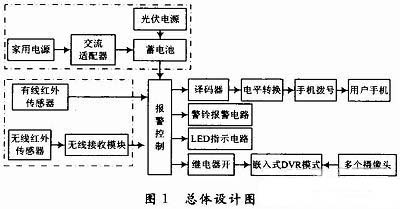
1.1 Power Supply Module
(1) The photovoltaic power supply provides power for each wireless device and provides auxiliary power for the wired device.
(2) The household power supply connection transformer device and the battery constitute a power supply.
1.2 Infrared sensing module
The wireless pyroelectric infrared sensor utilizes a Fresnel lens to improve the sensitivity of the sensor and to make the detection range of the sensor directional, and is connected to the infrared sensing signal processing circuit and then to the digital interface of the alarm control host. The wireless sensor is fixed in a concealed position, connected to the photovoltaic power storage battery, and transmits the signal to the host computer through the wireless communication chip. A plurality of infrared ray devices form an infrared sensing network, and comprehensively process external signals through a wireless sensor network program.
1.3 GSM module
The module adopts the wireless dialing transmission module, and the alarm control host connects to the mobile dialer through the RS 232 serial port, and dials the user's mobile phone number according to a predetermined procedure.
1.4 Recording and alarm storage module
The embedded monitoring DVR module of the camera's large-capacity hard disk storage can be configured with a large-capacity hard disk as the front-end storage medium for ultra-long time monitoring. Multiple cameras store images with good authenticity and retain all recording information. In order to achieve weak current control of strong power, when the alarm control host sends a signal, the DVR module is controlled by the relay switch, and the camera automatically turns the recording on or off. When the system works, the alarm control host will issue an instruction to make the alarm alarm, and the LED indicator will light red at the same time; when the system is in sleep, the alarm will not alarm and the LED indicator will light green.
2 circuit design
2.1 main control circuit
The one-chip computer adopts ATM89's AT89S52, which integrates 256 B program running space, 8 KB FLASH storage space, supports up to 64 KB external storage expansion, clock frequency can be set between 0~33 MHz, and there are 4 groups of 32 on-chip resources. I/O control port, three 16-bit timers, eight vector two-stage interrupt structure, software set in low power mode, and watchdog and power-down protection. The main control circuit is shown in Figure 2.
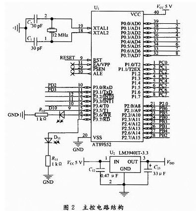
It works well in the wide voltage range of 4~5.5V, low power consumption, and also supports computer parallel port download. The AT89S52 is available in a variety of packages. The DIP-40 package is used in this design.
2.2 Photovoltaic power generation and home power supply interface circuit
The main unit uses a dual power supply of solar cells and a home 220 V power supply. When there is household electricity, the solar cell is smartly disconnected through the DC low voltage relay; when the household electricity is disconnected, the solar battery acts as a power source.
The solar cell is connected to the solar panel through a solar smart charger. The charger charges the battery when the sun is full, and automatically disconnects the battery when the battery is fully charged. In the case of sufficient sun, the charging current can reach more than 1 A, which fully meets the needs of the circuit.
2.3 GSM network access circuit
This system uses Siemens TC35 series GSM chip TC35i and GSM2/2 compatible, dual frequency (GSM900/GSM1800), RS 232 data interface, TC35i power supply module (AS IC), flash memory, ZIF connector, antenna interface, etc. Six parts. The module and the RF circuit and baseband are integrated to provide users with a standard AT command interface to provide fast, reliable and secure transmission of data, voice, short messages and faxes.
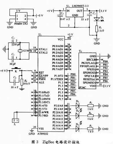
2.4 ZigBee protocol wireless communication circuit (slave)
The slave circuit is mainly based on the 2.4 GHz two-way wireless transmission module JF24C. The module realizes the data transmission function with a small volume, the rate can be up to 1 Mb/s, and has fast frequency hopping, forward error correction, CRC and other functions. . Through the signal of the controller, the information is transmitted through the electromagnetic wave, and the adjacent chip controls the corresponding JF24CJ to receive the data, thereby realizing the information transmission. The ZigBee circuit design module is shown in Figure 3.
2.5 power circuit and alarm, video monitoring circuit
Photovoltaic power supply and video monitoring control circuit shown in Figure 4.
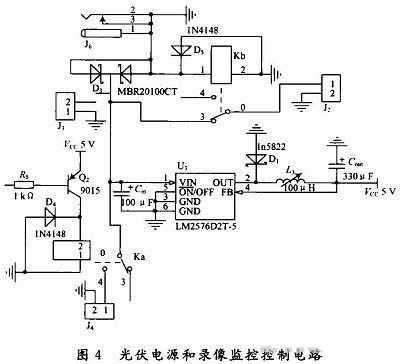
The alarm circuit uses a simple and efficient triode amplifying circuit to connect the buzzer or an alarm bell with a power of more than 100 dB.
The video monitoring circuit uses a weak current to control the strong DC relay, the coil is terminated with a single-chip microcomputer, and the DC current is terminated with a DVR.
3 software design
The flow chart of the slave programming algorithm is shown in Figure 5.
The main chip programming algorithm flow chart is shown in Figure 6.

4 Experimental results
The working environment of the device was simulated indoors. When the solar panel was exposed to outdoor sunlight (temperature 24 °C) 14 under direct sunlight, three slaves were coordinated to realize signal detection and data transmission.
Connect the battery to the indoor power socket, turn on the main controller switch, the LED interface displays "welcome to zzu" English characters, and the alarm phone number (1503819****) is set to go directly to the working mode. When approaching the slave slice 1 by about 3.5 m, an alarm signal is sent from the slice 1 and sent to the nearest slave slice 2, and an alarm signal is detected from the slice 2 and then forwarded to the host. When the host receives the alarm signal, the display shows the word "TERMINAL 1" and controls the GSM module to make a call to 1503819****. At the same time, the alarm sounds an alarm, the camera implements the recording function, and stores the data. Connect the battery to the solar panel, disconnect the power supply from the room, repeat the above actions, and achieve the same function. After 30 experiments, the alarm success rate was 28, no false positives.
5 Conclusion
After field testing, the system's alarm success rate is 93%, which can accurately implement the alarm function.
The system is a tentative and successful application of the ZigBee protocol and photovoltaic power generation in the home security system. It is expected that the above two technologies will have broader prospects in the smart home field.
Plastic Mesh,Black Plastic Mesh,Plastic Mesh Netting
Gabion,Welded Wire Mesh Co., Ltd. , http://www.nsweldedwire.com