Abstract : As the technology of bridges is getting higher and higher. The bridge deflection monitoring system is also getting higher and higher, and the existing bridge deflection monitoring system can no longer meet the requirements of current monitoring. The following is a design scheme of the bridge deflection wireless monitoring system using ZigBee technology. The software and hardware of the sensor nodes in the bridge deflection wireless monitoring system are designed, and the deflection data automatic monitoring and wireless transmission are realized.
With the continuous emergence of various types of long-span bridges, people pay more and more attention to the safety, durability and reliability of large-scale important bridges. The health monitoring and safety assessment of bridges have received more and more attention. Among the many parameters of bridge health monitoring, bridge deflection is an important indicator, which directly reflects the safety and reliability of the bridge. Existing bridge deflection monitoring systems usually use wired communication to form a network, which has the disadvantages of high cost, long construction period and vulnerability to the environment.
The emerging ZiZigBee technology is a two-way wireless communication technology with close proximity, low complexity, low power consumption, low speed and low cost. It is mainly used for data transmission between various electronic devices with short distance, low power consumption and low transmission rate, and typical applications with periodic data, intermittent data and low response time data transmission. gBee technology is a short-range wireless two-way communication technology. It has the advantages of simple protocol, low power consumption, large network capacity, short delay and low cost. It is especially suitable for small amount of data transmission, real-time performance and coverage. Wide monitoring system. Aiming at the shortcomings of the traditional bridge deflection monitoring system, this paper proposes the design scheme of applying ZigBee technology to the bridge deflection monitoring system, realizing the real-time monitoring and wireless transmission of bridge deflection data.
1 ZigBee comparison with other short-range wireless communication technologies
Zigbee is a wireless data transmission network platform consisting of up to 65,000 wireless data transmission modules. Each Zigbee network data transmission module can communicate with each other within the entire network. The distance between each network node can be Standard 75m unlimited expansion.
The short-range wireless communication technologies currently on the market mainly include: ZigBee technology, infrared technology, Bluetooth technology, UWB technology and Wi-Fi technology, etc., all of which have their own characteristics, compare the parameters of these short-range wireless communication technologies, See Table 1.

What is the self-organizing network used by ZigBee technology? A simple example can illustrate this problem. When a team of paratroopers airborne, each person holds a ZigBee network module terminal, and when they land on the ground, as long as they are within the communication range of the network module, they automatically seek each other. A connected ZigBee network can be formed soon. Moreover, due to the movement of people, the contact between them will change. Therefore, the module can also refresh the original network by re-finding the communication objects, determining the contact with each other.
ZigBee is a wireless connection that operates at 2.4 GHz (global), 868 MHz (popular in Europe) and 915 MHz (popular in the US) with up to 250 kbit/s, 20 kbit/s and 40 kbit/s transmissions. The rate, its transmission distance is in the range of 10-75m, but can continue to increase. As a wireless communication technology, ZigBee has the following characteristics:
(1) Low power consumption: Because ZigBee has a low transmission rate, the transmission power is only 1mW, and the sleep mode is adopted, the power consumption is low, so the ZigBee device is very power-saving. It is estimated that ZigBee devices can last up to 6 months to 2 years with only two 5th batteries, which is beyond the reach of other wireless devices.
(2) Low cost: The initial cost of the ZigBee module is around $6, which is estimated to drop to $1.5-2.5 soon, and the ZigBee protocol is royalty-free. Low cost is also a key factor for ZigBee.
(3) Short delay: The communication delay and the delay from the sleep state are very short. The typical search device delay is 30ms, the sleep activation delay is 15ms, and the active device channel access delay is 15ms. ZigBee technology is ideal for time-critical wireless control applications such as industrial control applications.
(4) Large network capacity: A star-shaped Zigbee network can accommodate up to 254 slave devices and one master device. Up to 100 ZigBee networks can exist simultaneously in one area, and the network composition is flexible.
(5) Reliable: A collision avoidance strategy is adopted, and dedicated time slots are reserved for communication services requiring a fixed bandwidth, avoiding competition and collision of transmitted data. The MAC layer uses a fully acknowledged data transmission mode, and each transmitted packet must wait for the recipient's confirmation message. If there is a problem during the transfer, you can resend it.
(6) Security: ZigBee provides a packet integrity check function based on cyclic redundancy check (CRC), which supports authentication and authentication. The AES-128 encryption algorithm is adopted, and each application can flexibly determine its security attributes.
2 Bridge deflection wireless monitoring system design
ZigBee devices have powerful device networking capabilities that support three wireless network topologies, namely star, tree, and mesh. The star structure is simple, but all nodes in the network can only communicate with the coordinator, which is easy to cause information congestion, increase packet loss rate and power consumption of the coordinator. Both the tree cluster structure and the mesh structure belong to a point-to-point structure, and communication can be performed between any two devices, thereby reducing the power consumption of the coordinator and increasing the communication range, but the mesh structure is complicated and the cost is high.
The bridge deflection wireless monitoring system consists of a bridge deflection sensor node, a router node, a coordinator node, a field computer and a remote monitoring center computer. The system block diagram is shown in Figure 1.

The bridge deflection sensor node is a key part of the bridge deflection wireless monitoring system and is also the focus of this paper. Firstly, the image signal is collected by the CCD image sensor, and then sent to the MCU for processing by the A/D conversion to obtain the deflection data; then the deflection data is converted into the ZigBee communication protocol data packet by the ZigBee communication module, and transmitted to the nearest router node.
The router node drives the routing algorithm according to the routing table, selects the optimal communication path, and transmits the data packet to the ZigBee coordinator through other ZigBee routing modules in a multi-hop communication manner.
After receiving the data packet, the coordinator sends the confirmation primitive to the node that sends the data according to the original path, implements handshake communication, completes a complete ZigBee wireless communication, and uploads the received deflection data to the field computer through the serial port. It is convenient for testing and maintenance of on-site staff. The on-site computer aggregates the acquired deflection data and transmits the collected data to the computer of the remote monitoring center through the optical cable.
3 sensor node hardware design
The hardware of the bridge deflection sensor node is mainly composed of an image sensor module, a microprocessor module, a communication module and a power module, as shown in FIG. 2 . The microprocessor module is the core module of the node, and is responsible for managing the coordination of each module in the node, such as generating the pulse signal of the TCD1209D, processing, saving and transmitting the deflection image signal collected by the TCD1209D, starting the CC2430 communication module to send and receive data, etc. . The power module is responsible for providing reliable power to each module of the sensor node. For the reason of space, the following mainly introduces the circuit design of the micro processing module and the CC2430 wireless communication module.

3.1 microprocessor module circuit design
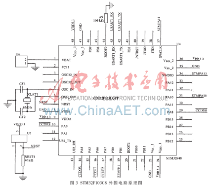
The microprocessor chip of the bridge deflection sensor node uses STMicroelectronics' STM32F103C8 chip. It uses a 32-bit Cortex-M3 core with a maximum operating frequency of 72 MHz. The Cortex-M3 core is the smallest ARM core ever, with a Harvard architecture with a 3-level instruction pipeline; with ultra-low power consumption of only 0.19 mW/MHz; Compatible with the Thumb-2 instruction set, with 16-bit code density; 35% faster than ARM7TDMI core, but 45% less code, saving storage space; extensive development tools, low development cost, cycle short. The STM32F103C8 is available in LQFP package with 48 pins. Internal resources include [2]: 64 KB of flash memory and 20 KB of RAM; 2 SPI communication interfaces; 2 I2C interfaces; 3 USART interfaces; 11 timings Four of them can be used to generate PWM; two 12-bit 10-channel ADCs improve the accuracy of data acquisition.
The peripheral circuit design of STM32F103C8 is shown in Figure 3. The periphery is powered by DC 3.3 V. The external battery socket can be used to ensure normal operation of the RTC when power is suddenly lost. It sends and receives wireless communication data through the serial port pins. It generates the 5-channel drive pulse signal (SH, RS, CP, φ1, φ2) of TCD1209D by advanced timer and general-purpose timer. Its advanced timer outputs one PWM signal from pin 29, and is pulled up by level and 74LS04. The pulse signal SH is obtained backward; its general-purpose timer 3 (TIM3) generates a set of complementary PWM pulse signals, which can generate drive signals φ1 and φ2 after being pulled up by level; its general-purpose timer 2 (TIM2) is from pin 10 The PWM signal is outputted, and the RS pulse signal is obtained after the level pull-up and 74LS04 are reversed. The RS and CP timing cycles are the same, but the CP is delayed by 100 ns than the RS, and the hardware gate circuit can be used for delay and the pulse signal CP can be generated.

3.2 Wireless Communication Module
ZigBee wireless communication chip selects CC2430 chip which conforms to ZigBee standard protocol, which has the advantages of stable performance, low power consumption and few peripheral devices. The CC2430 chip is the world's first true SoC chip supporting the ZigBee protocol provided by TI. It integrates ZigBee RF front-end, memory and microcontroller in a single chip, using an 8-bit MCU core with programmable up to 128 KB. Flash memory and 8 KB of RAM memory, including analog-to-digital converter, four timers, AES-128 coprocessor, watchdog timer, sleep mode timer for 32.768 kHz crystal.
The CC2430 requires only a few peripheral components to implement the signal transceiving function. The schematic diagram of the peripheral configuration circuit is shown in Figure 4. The CC2430 peripheral circuit includes: a power supply filter circuit, a crystal oscillator circuit, a communication interface circuit, a reset circuit, an antenna circuit, and a debug interface circuit. The CC2430 has its own internal voltage regulator. By inputting 3.3 V DC from pin 41 (AVDD_DREG), a stable 1.8 V DC voltage can be output from pin 24, so the CC2430 externally requires only 3.3 V DC. In order to ensure the stability of the external power supply, the circuit board is powered by 5 V DC voltage and output 3.3 V DC voltage after AMS1117. Therefore, 0.1 μF is selected. And 1 μF filter capacitor. The crystal oscillator circuit consists of an external 32.768 kHz, 32 MHz crystal oscillator and load capacitor. The system clock source of the CC2430 is set by setting the OSC bit of the CLKCON register, and 32.768 kHz is the system sleep clock. The antenna uses a single-stage unbalanced antenna to connect the balun to make the antenna performance better. The balun in the circuit consists of a capacitor and an inductor. The internal T/R switching circuit is used to complete the exchange between the LNA and the PA. The asynchronous serial communication method is adopted between the CC2430 and the MCU. The 7th bit of the U0CSR register in the CC2430 is configured as the UART communication mode, and then the special function register (SFR) is configured, and the pins 13 and 14 are respectively set to the RX and TX of the USART. It is connected with the serial port transceiver pin of STM32F103C8, which realizes the function of exchanging data and receiving commands with MCU. The pins of the debug interface circuit are 45 (P2_2) and 46 (P2_1).

4 sensor node software design
The software part of the bridge deflection sensor terminal node is designed with IAR Embedded Workbench as the development platform. IAR is a complete collection of integrated development tools, including code editors, project builders, C/C++ compilers, connectors, and C-SPY debuggers. IAR supports software writing and debugging of the Cortex-M3 core microprocessor and ZigBee protocol stack, as well as the use of the Jlink emulator and C51RF emulator. The node's ZigBee protocol stack uses the free protocol stack provided by TI, and uses the development kit provided by Chipcon when the network is set up.
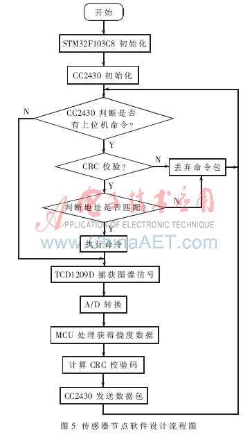
The sensor terminal node software is written in C language and uses modular programming. It is mainly composed of three modules of sensor node initialization, acquisition deflection data and wireless communication module sending and receiving data. The software design flow chart is shown in Figure 5. STM32F103C8 chip initialization includes: defining buffers, configuring clocks, configuring GPIO pins, interrupt configuration, serial port configuration, DMA configuration, and timer configuration. The CC2430 chip initialization includes: starting the voltage regulator, configuring the clock, configuring the four registers of the 8051, and configuring the A/D.

5 applications
Through the application of Xiaogou Bridge in Shanxi Yinzhou Expressway Company, the reliability and stability of wireless communication in the application of the system are verified.
First select the network topology. Since the small trench bridge spans 100 m per span, and the reliable communication distance of the ZigBee communication module is ≥100 m (related to the antenna and transmit power), the deflection data of the side span needs to be transmitted to the coordinator hop by hop through the router, so the tree cluster is adopted. Type network topology.
Then set up the wireless sensor network node, as shown in Figure 6. The 7 deflection sensor nodes are placed in the bridge deflection monitoring of each span, which is responsible for collecting the deflection information of each span; 6 router nodes are placed 5 to 10 m apart from each span deflection sensor node, and the distance between adjacent routers is 75~ 90 m; 1 coordinator node is fixed in the middle span of the Xiaogou Bridge, responsible for establishing the network, assigning the network address, and uploading the data collected by each sensor node to the field computer from the serial port.

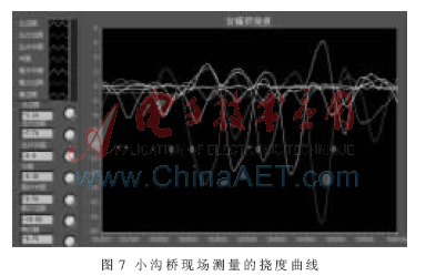
Finally, the on-site computer receives the deflection data of each span through the serial port, and runs the software written in LabVIEW [3] language to display and save the deflection data of each span of the bridge. The deflection curve of the right bridge collected on site is shown in Fig. 7. The different curves represent the deflection of each span when the vehicle passes. Each curve is continuous, with no obvious discontinuities and jumps, indicating that the wireless communication system has reliable data transmission and strong stability.

ZigBee technology makes up for the shortcomings of low-cost, low-power and low-rate short-range wireless communication markets, and is an indispensable component of wireless sensor networks. The main innovation of this paper is to apply ZigBee technology to the bridge deflection monitoring system, and realize the real-time data acquisition and wireless transmission of system data by using the high performance and low power consumption of Cortex-M3 core. It has strong stability, good mobility and low cost. Etc. In this paper, ZigBee wireless network technology is applied to the bridge deflection monitoring system, which effectively solves the shortcomings such as large wiring workload and long construction period in the original system.
:
Sulfate,Sulfate Free Shampoo,Sulfate Charge,Sulfate Ion Formula
Chemicals ,Fertilizer Co., Lt d , http://www.nbfertilizer.com
