
This paper briefly describes the composition principle of the electrical fire monitoring system, and analyzes the design basis and related specifications of the electrical fire monitoring system in the application. Finally, through the introduction of Ankerui residual current electric fire monitoring system in the Zhoukou Radio and TV Tower project, the realization of the function of the electrical fire monitoring system and its significance are expounded.
Yang Junjun An Kerui Electric Co., Ltd. Shanghai Jiading
0 Overview
Zhoukou Radio and TV Tower is located at the intersection of Qiyi Road and Zhoukou Avenue in Zhoukou City. It covers an area of ​​54.6 acres, with a construction area of ​​8376.8m2, a steel structure of about 5200 tons, a total investment of about 200 million yuan, and a total height of 286.57 meters. After the completion of the project, it is ranked first in the height of the radio and television transmission tower of the provincial government of our province, and its height is second only to the building height of 388 meters, the world's tallest steel structure tower - Henan Radio and Television Tower. The project is 46 ARCM200L series instruments on the floor of the radio and television tower in Zhoukou City, distributed in the 286-meter-high TV tower. This project is mainly responsible for monitoring the leakage status of the incoming line distributed on the floor distribution box, and promptly reminding the duty room of the control room to prevent the occurrence of electrical fires.
At the scene of the Zhoukou Radio and TV Tower, there are 46 current ARCM200L residual current meters installed in the floor distribution box. The field instrument is connected to the Acrel-6000/B wall-mounted electrical fire monitoring system of the control center by bus.
1 reference standard
In recent years, in order to increase the intensity of electrical fire monitoring and prevention, the state has successively formulated or revised a number of relevant standards and regulations to strengthen the prevention of electrical fires. There are:
1.1. GB50045-95 (2005 edition) "Code for Fire Protection Design of High-rise Civil Buildings", which stipulates in Article 9.5.1 that a fire alarm system should be installed in places with high fire risk and dense personnel in high-rise buildings.
1.2. GB50016-2006 "Code for Fire Protection of Building Design", as specified in Article 11.2.7: The following places should be equipped with a residual current action electrical fire monitoring system. These venues include various types of theaters, galleries, warehouses, residential communities, hospitals, shops, schools, and more.
1.3. The relevant provisions of the national standard "Building electrical fire prevention requirements and testing methods" also clearly require that "the residual current action protector that automatically cuts off the power or alarm should be set at the power incoming end".
1.4. The products of the electrical fire monitoring system shall meet: GB14287.1-2005 "Electrical Fire Monitoring Equipment", GB14287.2-2005 "Residual Current Electric Fire Monitoring Detector", GB14287.3-2005 "Measurement Temperature Electric Fire Monitoring and Detection" 》
1.5. The installation and operation of the electrical fire monitoring system shall meet the requirements of GB13955-2005 "Installation and operation of residual current action protection device"
1.6. The power supply of the electrical fire monitoring system shall meet the requirements of GB50052 "Design Specifications for Power Supply and Distribution Systems"
1.7. The design of the electrical fire monitoring system shall meet the requirements of the Design Method of Electrical Fire Monitoring System (Interim Provisions)
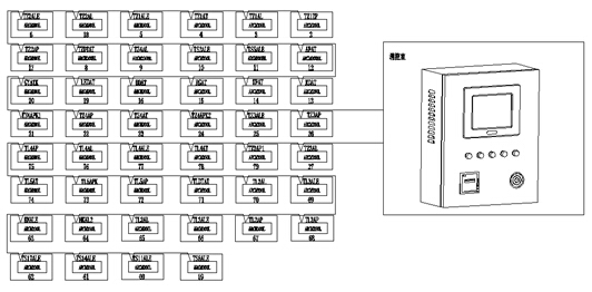
2 system components
The electrical fire project of Zhoukou Radio and TV Tower consists of electrical fire monitoring background, electrical fire detector and leakage current transformer.
The communication bus of this project is connected to two communication buses. After the bus is connected hand in hand in the floor, it is connected to the wall-mounted background to form the aorta of the electrical fire system. The leakage current transformer in the cabinet is connected to the leakage detector through the current line, and the leakage detector displays the leakage condition in real time. The above describes a set of electrical fire monitoring systems with stable signal and reliable accuracy. The system networking is divided into three layers:
1) Station management
The management of the station control management system for the electrical fire monitoring system is the direct window of human-computer interaction and the uppermost part of the system. Mainly composed of system software and necessary hardware equipment, such as touch screen, UPS power supply and so on. The monitoring system software calculates, analyzes, and processes various types of data information on the site, and responds to the on-site transportation situation by means of graphics, digital display, sound, and indicator lights.
Monitoring host: used for data collection, processing, and data forwarding. Provides data interfaces for system management, maintenance, and analysis within and outside the system.
UPS: Ensure the normal power supply of the computer monitoring system, and ensure the normal operation of the station management management equipment when the whole system has power supply problems.
The background monitoring device is set in the control room.
2) Network communication layer
Communication medium: The system mainly adopts shielded twisted pair cable, realizes real-time communication between field device and host computer by RS485 interface and MODBUS communication protocol.
3) Field device layer
The field device layer is a data acquisition terminal, mainly for the ARCM200L series of residual electrical fire monitoring detectors.
The system structure topology is as follows:
3. Electrical fire equipment

3.1, Acrel-6000/B electrical fire monitoring background:
The main technical parameters
power supply:
1 rated working voltage AC220V (-15% ~ +10%)
2 Backup power supply: When the main power supply is under voltage or power failure, maintain the monitoring equipment working time ≥ 4 hours
Working system:
24-hour work schedule
communication method:
RS485 bus communication, Modbus-RTU communication protocol, transmission distance 1km, can extend communication transmission distance through repeater
Monitoring capacity:
1 Monitoring equipment can monitor up to 200 monitoring units (detectors)
2 can be connected with ARCM series monitoring detector
Monitoring alarm items:
1 Residual current fault (leakage): fault unit attribute (part, type)
2 Temperature alarm (over temperature): Fault unit attribute (part, type)
3 Current fault (overcurrent): Fault unit attribute (part, type)
Monitoring alarm response time: ≤30s
Monitoring alarm sound pressure level (A weighting): ≥70dB/1m
Monitoring alarm light display: red LED indicator, red light alarm signal should be maintained until manual reset
Monitoring alarm sound signal: can be manually eliminated, can be started again when there is alarm signal input again
Fault alarm item:
1 The communication cable between the monitoring device and the detector is open or shorted.
2 Monitoring equipment main power supply undervoltage or power failure
3 The cable between the charger that charges the battery and the battery is broken or shorted.
Fault alarm response time: ≤100s
Monitoring alarm sound pressure level (A weighting): ≥70dB/1m
Monitoring alarm light display: yellow LED indicator, yellow light alarm signal should be kept until troubleshooting
Fault alarm sound signal: can be manually eliminated, can be started again when there is an alarm signal input again
The normal operation of the non-faulty loop is not affected during the fault
Control output:
Alarm control output: 1 set of normally open passive contacts, capacity: AC250V 3A or DC30V 3A
Self-test items:
1 Indicator check: alarm, fault, operation, main power, standby power indicator
2 display check
3 audio device inspection
Self-test time ≤60s
record:
1 Record content: record type, time of occurrence, detector number, area, fault description, can store no less than 20,000 records
2 record query: query according to the date, type and other conditions of the record
Operational rating:
1 Daily duty class: real-time status monitoring, event record query
2 Monitoring operation level: real-time status monitoring, event record query, detector remote reset, device self-test
3 System management level: real-time status monitoring, event record query, detector remote reset, device self-test, monitoring device system parameter query, monitoring device module detection, operator addition and deletion
Environmental conditions used:
1 Workplace: Fire control room, manned substation (distribution room), wall on room where someone is on duty
2 Working environment temperature: 0 ° C ~ 40 ° C
3 Working environment relative humidity: 5% ~ 95% RH
4 Altitude: ≤2500m
3.2, ARCM200L series instruments
The ARCM200L residual current type electrical fire monitoring detector is designed for TT and TN systems below 0.4kV. It monitors and manages fire risk parameters such as residual current, wire temperature, over current and over voltage in the distribution circuit. Thereby preventing the occurrence of electrical fires and real-time monitoring of various power parameters, providing accurate data for energy management. The product adopts advanced microcontroller technology, with high integration, small size, convenient installation, intelligent, digital and networked. It is an ideal choice for building electrical fire prevention monitoring and system insulation aging prediction. The product complies with the standard requirements of GB14287.2-2005 "Electrical Fire Monitoring System Part 2: Residual Current Electrical Fire Monitoring Detector".
4 system function
4.1. Monitoring alarm function:
The monitoring equipment can receive the leakage and temperature information of multiple detectors, and emit an audible and visual alarm signal when the alarm occurs. At the same time, the red “alarm†indicator on the device lights up, the display indicates the alarm location and alarm type, and the alarm time is recorded. The sound and light alarm is always maintained. Until the display is reset by pressing the display "Reset" button. The audible alarm signal can also be manually removed using the display "Muffler" button.
4.2. Fault alarm function
Communication failure alarm: When a communication failure occurs between the monitoring device and any of the connected detectors, the corresponding detector in the monitoring screen displays a fault indication, and the yellow “fault†indicator on the device lights up, and a fault alarm sound is emitted. .
Power failure alarm: When the main power or backup power fails, the monitoring device also emits an audible and visual alarm signal and displays the fault information. You can enter the corresponding interface to view the detailed information and release the alarm sound.
4.3. Self-test function
Check that all status indicators, display, and speakers in the device are normal.
4.4. Alarm record storage query function
When leakage, over-temperature alarm or communication or power failure occurs, the alarm part, fault information, alarm time and other information are stored in the database. When the alarm is cancelled or the fault is eliminated, the same is recorded. Historical data provides a variety of convenient and fast ways to query.
4.5. Power function
When the main power supply has a power failure, undervoltage, etc., the monitoring equipment can automatically switch to the standby power supply. When the main power supply returns to normal power supply, it automatically switches back to the main power supply, ensuring continuous and smooth operation of the monitoring equipment during the switching process.
4.6. Detector control function
Remote monitoring of all detectors connected to the unit is possible through monitoring software operation.
4.7. Authority Control Function
In order to ensure the safe operation of the monitoring system, the monitoring device software operation authority is divided into three levels, and different levels of operators have different operation rights.
5 Conclusion
Zhoukou City Radio and Television Tower electrical fire monitoring system consists of electrical fire monitoring device Acrel-6000/B, leakage fire detector leakage fire detector ARCM200L. The Acrel-6000 electrical fire monitoring system is an industrial grade that is independently developed by the company to receive field devices such as residual current electrical fire detectors to achieve alarm, monitoring, control, and management of protected electrical circuits. Hardware/software system. The system is applied to the fire control center of large shopping malls, living quarters, production bases, office buildings, shopping malls and other areas, and telemetry, remote adjustment, remote control and remote signaling of detectors scattered in the building are convenient for monitoring and management. The system uses a standard Modbus field bus to connect detectors with communication functions. When the detected parameter in the field protection circuit exceeds the alarm set value, it can send out alarm signals and control signals, can indicate the alarm part and save the alarm. information. The field instrument is connected to the Acrel-6000/B wall-mounted electrical fire monitoring system of the control center by bus. The system has the advantages of convenient installation and transportation, high cost performance and convenient maintenance.
references
[1]. Ren Zhicheng Zhou Zhong. Principles and Application Guidelines of Power Electrical Measurement Digital Instrumentation [M]. Beijing. China Electric Power Press. 2007. 4
[2]. Zhou Zhong. Application of power meter in electric energy metering of large public buildings [J]. Modern Building Electric 2010. 6
About the author: Yang Junjun, female, undergraduate. Position: Now working for Ankerui Electric Co., Ltd., contact number, mobile phone, QQ
Http://news.chinawj.com.cn Editor: (Hardware Business Network Information Center) http://news.chinawj.com.cn
Kitchen utensils are various. Besides kitchen knives, there are also kitchen scissors and chicken bone forceps that can be used to cut chicken bones, Bottle Opener, pizza peel, Pizza Cutter, kitchenware,cooking tools, Egg Whisk ,Sausage Guillotine,cutting board, mango cutting, watermelon cutting, pineapple cutting, gourd grater,garlic press, etc. The type of kitchen scissors and chicken bone forceps is rich, the choice is much.There are many types of bottle opener. There are many types of kitchenware and cooking tools, including nylon kitchenware and cooking tools, silicone kitchenware and cooking tools, stainless steel kitchenware and cooking tools, wooden kitchenware and cooking tools etc..
Cooking Utensils,Kitchen Utensil Set,Kitchen Tools,Cooking Accessories
Yangjiang Yangdong Hongli Industries Co.,Limited , https://www.hongli-industry.com