Research on Partial Discharge Transmission Characteristics of Coil Insulation of Electric Power Equipment LIU Shao-ke1, ZHANG Kui-kui2 (1. College of Mechanical and Electrical Engineering and Automation, National University of Defense Technology, Changsha 4100732, China. Hunan Vocational College of Transportation, Changsha 410004, Hunan, China) Size, waveform and absolute internal discharge size There is a big difference between waveforms. In this paper, the characteristics of the partial discharge of the coils in power equipments are studied. The results of the relevant researches and the results of the experimental observations are as follows.
The coil insulation of power equipment is the key to its normal operation.
Initial coil local defects, such as incomplete filling of the impregnating resin, cause gaps between the gallium insulation and the tank insulation, causing partial discharges.
Once the partial discharge occurs, it will cause chemical corrosion and local overheating, resulting in further deterioration of the insulation, and eventually lead to equipment failure. Therefore, the partial discharge measurement is an important method for diagnosing the insulation condition of power equipment coils, and gradually attracts people's extensive attention.
Partial discharge usually appears as a pulsed current that is transmitted along the coil conductor. Due to the complexity of the coil structure, the size and waveform of the partial discharge measured by the conventional method are often greatly different from the actual discharge size and waveform within the insulation. By analyzing the partial discharge pulse current in the coil transmission, it helps to understand the correspondence between the partial discharge pulse current (apparent discharge current) at the external monitoring point and the amount of the internal discharge pulse current (actual discharge current) in the insulation. , And further positioning the power supply point. For the first time, this paper studies the partial discharge transmission characteristics of coil insulation in power equipment. The relevant research results are consistent with the experimental observations.
1 coil insulated partial discharge circuit model When the partial discharge current is transmitted along the coil conductor, in addition to the conductor resistance, there are various distributed capacitance and distributed inductance. Considering the distributed capacitance and distributed inductance, it can be represented by the L+C+K chain circuit shown. Medium G and C respectively represent the conductance and capacitance of the conductor to the ground (core), and R and L represent the resistance and inductance of the conductor, respectively. For a chain link, it represents a coil. When ignoring the change of each parameter with åŒ, it can also represent a åŒ. Single chain links one by one successively concentrated on the parameters L-C + K chain circuit There are two types of coil insulated partial discharge in the circuit, they are the coil internal inter-turn discharge and coil-to-ground (core) discharge.
The analysis results of the two discharge forms are similar, so we will analyze the second discharge form below. In order to not lose the generality, set the second half of chain link to ground discharge, with is represents the discharge current, as shown.
The discharge of the second half of the chain to the ground occurs in the local area, so CiC2 can be further simplified. The discharge current is transmitted in the coil branch in two paths: 1 and the is1 is directly transmitted to the branch via the coil branch. 1: Liu Shaoke £19A3ca)e Male Associate Professor I P Shi I Research direction Magnetic levitation control Mn motor control system and detection nghtsreserved, http:// The above formula is written as the matrix equation is as follows: Here = is the branch current coefficient matrix, which is the capacitance matrix, is The conductivity matrix, which is a diagonal matrix.
Also for us, we can list the branch voltage equation: = 10 = diag is the resistor matrix, = diag is the inductance matrix, which is a frequency of 1 effect, f = 4/Tmax is used in the calculation, T is the simulated partial discharge pulse rise time. The line inductance is generally 1 ~ 1.5H/m, take L = PH here, consider the insulation of the electrical machinery is new, so ignore the influence of G.
The partial discharge pulse is simulated by the following double exponential pulse current.
o(7) It is obvious that the discharge current pulse at the actual position is is is is1. Solving the relationship between is and io accurately involves solving the three-phase circuit network. This solution is very complicated. Considering that is2 is transmitted through the coil to the high voltage terminal lead, its timing will be later than is1 (especially when the discharge point is close to the high voltage terminal), and the amplitude is attenuated (especially when the neutral point of the 3-phase coil is grounded ), a reasonable approximation considers that is1=is2, so that is1=is/2, so the above-mentioned conclusion about m divided by 4 back, soil and earth plus one: the seven analysis is bu io is also suitable for is Io. (next to page 7) array.
Using the reduced-order method, Equation (4) can be converted into a state equation after = dt, and then solved using numerical methods.
3 Partial Discharge Transmission Simulation Calculation In order to understand the transmission characteristics of the partial discharge current in the coil, the formula (4) was used to calculate the stator coil of an actual motor, and the calculation results were compared with the experimental observation results. The calculation results of the motor's ground discharge simulation showed that different T, T2, and the number of chain links N indicate that an oscillating current is still established in the coil branch even under the non-oscillating pulse current. The steeper the rising edge of the pulse (mainly dependent on T2), the greater the oscillation amplitude and the higher the oscillation frequency. In the measurement of the actual PD pulse, it is found that at the measurement point of the lead-out line, the PD is mostly in the form of an exponentially decaying oscillation whose oscillations are rich in high frequency components, indicating that the actual PD T2 is usually very small.
At the falling edge of the pulse, the oscillating current basically reaches a stable decaying oscillation state, ie, the oscillating current attenuates oscillation with the source pulse current isl as an axis.
The oscillating current component of the current is at the coil outlet end is determined by the equivalent circuit, and the more the number of links (the larger N is, ie, the farther the discharge point is from the coil outlet end), the lower the oscillation frequency.
The amplitude of the oscillating current component of the current io at the outlet end of the coil may be greater than the amplitude of the oscillating current component at the internal point, which means that the magnitude of the oscillating component of the pulse is not reduced but it is further increased when the pulse is passed to the coil terminal.
The above calculation results are consistent with the experimental observations.
Obviously, the amount of charge between the source is1 and the response io is not the same, and the total amount of charge that is flowing through is1 and io, respectively, is the duration. This completes the design of the ASIC chip of the time controller, and it is necessary to access the periphery of the chip. Power supplies, pulse signals, displays, etc. form a time-controlled hardware system.
3 Concluding remarks The use of advanced EDA software and hardware description language, with the help of a complex programmable logic device CPLD to achieve the design of the time controller, fully embodies the modern digital circuit design system chip design, systematic design of chip design ideas, breaking the traditional electronics The system's design mode enables rapid system development, low cost, and greatly improved system performance.
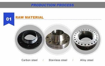
HANMAC is Manufacturer & Supplier of premium quality range of Aluminum Blind Flange. Aluminum 5083 Blind Flange is also called flange cover. It is a flange without holes in the middle for sealing the pipe plug.
Every process of Aluminum 1060 Blind Flange will be checked by responsible QC which insures every product's quality.
We welcome small quantity order for Aluminum 6061 Blind Flange
Our production scope: ASTM/ASME/ANSIB16.5, B16.47, ASME/ANSIB16.48 flange
Size: 1/2"-120" (DN15-DN3000)
Pressure: Class150-Class2500
Facing RF/FF / RTJ
Standard: ASTM/ASME/ANSIB16.5, ASME/ANSI B16.3and B16.47, ASME/ANSIB16.42, JIS/KS (5K, 10K, 16K, 20K), DIN2633, DIN2634, DIN2635,EN1092,BS4504,
Inspection: In house and third party
Document: MTC Comply with EN10204 3.1 can be provided prior to shipment


Aluminum Blind Flange
Aluminum 1060 Blind Flange, Aluminum 5083 Blind Flange, Aluminum 6061 Blind Flange, Aluminum Alloy Blind Flange
HEBEI HANMAC MACHINE CO., LTD. , https://www.chinahanmac.com
